DX7 Sound Chip Reverse Engineered
US A close look at the YM212805 10/12/21
|
We recently took a look at the DCOs in the Roland Juno, courtesy of Stargirl - and this time it's the turn of the DX7 and it's YM212805 OPS Operator chip. In what is an immensely impressive amount of research and detail, Ken Shirriff covers the operation of the sound chip starting out with the following mind-blowing process:
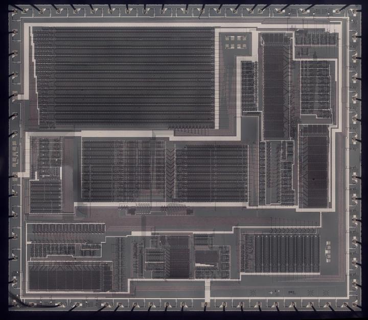
I created the high-resolution die photo below by compositing over a hundred microscope photos. Around the edges, you can see the 64 bond wires attached to pads; these connect the silicon die to the chip's 64 pins. The chip has one layer of metal, visible as the whitish lines on top. (Power and ground are the thick metal lines.) Underneath the metal, the polysilicon wiring layer appears reddish or greenish. Finally, the underlying silicon is grayish. The overall layout of the chip is dense rectangles of circuitry with the space between them used for signal routing. I will discuss these circuitry blocks in detail below.
He details the circuitry blocks contained within the chip, going into a frankly astonishing level of detail. It's not only an incredible explanation of the seemingly magical workings, it's equally a fascinating look at the inside of a microchip!
Ken has also done an even more in depth look at the exponential circuit within the sound chip, providing an even greater level of explanation there. https://www.righto.com/2021/11/reverse-engineering-yamaha-dx7_28.html
Head over to Ken Shirriff's blog for more computer history, restoring vintage computers, IC reverse engineering, and plenty more: https://www.righto.com/2021/11/reverse-engineering-yamaha-dx7.html
About the author [midierror]: midierror makes nifty Max For Live devices, innovative music hardware, award winning sample packs and hosts a podcast speaking to people in the music world.

- The History of Drum Machines 26-Apr-24
- Neutone Morpho V1 Released 26-Apr-24
- The MiniMoog Book Gets Funded 25-Apr-24
- Avid's Sibelius & Bad Interface Design 25-Apr-24
- Why Do Bells Sound Out of Tune? 25-Apr-24
Even more news...
Want Our Newsletter?
More Stories:

More...
 How Influential Were The Yellow Magic Orchestra?
Overview of boundary-pushing electronic group
 6 Instruments Fatally Flawed at Release
These synths took a little time to reach their potential

Pittsburgh Modular's latest release
 3 Home Keyboards that are Actually AWESOME Synths!
Not somewhere you usually look...

Aodyo Loom
 Moog At The Super Bowl
The Avila Brothers talk about their journey to the recent Super Bowl Halftime Show